ALSTECH AL-KTx2 Amplificador Valvulado Monobloco de 160W rms, ultralinear, push-pull, high end AB com KT150 ( Push Pull Tube Amplifier with 2x KT150 Tubes & Others)
ALSTECH AL-KTx2
АЛЬСТЕК AL-KTx2
Amplificado ultralinear push-pull high end
, com estágios de saída em classe AB com válvulas do tipo KT 150
Ultralinear push-pull high end amplifier , with class AB output stages with KT 150 type tubes
Ультралинейный двухтактный усилитель высокого класса с выходными каскадами класса AB на лампах типа KT 150
Este amplificador de potência de áudio utiliza duas válvulas KT150, numa configuração de saída push-pull em classe AB. A potência de saída obtida situa-se na casa de 160 W, com baixissíma distorção e uma banda larga. Sendo a KT150 é uma versão mais potente e mais moderna da antiga e conhecida KT88. Tendo este circuito uma reprodução sonora excelente e elevado rendimento, com o custo de montagem baixo em comparação ao valor de um equipamento comercial equivalente.
This audio power amplifier uses two KT150 tubes in a class AB push-pull output configuration. The output power obtained is around 160 W, with very low distortion and a wide bandwidth. Being the KT150 it is a more powerful and more modern version of the old and well known KT88. This circuit has excellent sound reproduction and high performance, with a low assembly cost compared to the value of an equivalent commercial equipment.
В этом усилителе мощности звука используются две лампы KT150 с двухтактной выходной конфигурацией класса AB. Полученная выходная мощность составляет около 160 Вт с очень низким уровнем искажений и широкой полосой пропускания. Будучи KT150, это более мощная и современная версия старого и хорошо известного KT88. Эта схема имеет отличное воспроизведение звука и высокую производительность при низкой стоимости сборки по сравнению со стоимостью эквивалентного коммерческого оборудования.
Desenvolvido por:
Eng. André Luiz de Lima Parreira Rodrigues (14) 99134-0330,
email: andrelimarodrigues@gmail.com
Youtube: Alstech Valvulados e Transformadores
Uma breve descrição do autor. Engenheiro eletrônico de formação,
residente em Lins/SP, atuo na área de áudio há 30 anos. Com conhecimento
elevado sobre valvulados e amplificadores. Decidi a trabalhar com
válvulas, pelo simples fato de com um circuito extremamente simples se
comparado aos de estado sólido podemos conseguir uma reprodução de nível
excelente e agradável a nossos ouvidos. Infelizmente a indústria
nacional e também estrangeira não fabrica a preço acessível um
equipamento decente. Temos que gastar rios de dinheiro, em busca do som
perfeito, muitas vezes pagando pequenas fortunas em caixas,
amplificadores e componentes de sistema importados. Nem sempre são bons,
mas acabamos sem opção e levados pelo efeito psicológico, do preço!
Tive oportunidade de experimentar praticamente a gama quase completa dos
equipamentos nacionais na fase de ouro (1970-1990), acredito que
exagerei muito esta data. Também experimentei quase todas as marcas
importadas até o momento. Hoje estou utilizando um belo par de torres
importadas, um SACD, este amplificador de potência do artigo e um pré
amplificador valvulado que em breve dividirei com os leitores o projeto
deste. A intenção deste artigo é proporcionar a quem tiver como
realizar, um equipamento de nível high end a um preço acessível.
A brief description of the author. Electronic engineer, residing in Lins/SP, I have been working in the audio area for 30 years. With high knowledge about tubes and amplifiers. I decided to work with tubes, for the simple fact that with an extremely simple circuit compared to solid state ones we can achieve an excellent level reproduction that is pleasant to our ears. Unfortunately, national and foreign industry does not manufacture decent equipment at an affordable price. We have to spend lots of money in search of the perfect sound, many times paying small fortunes in imported boxes, amplifiers and system components. They are not always good, but we end up with no option and carried away by the psychological effect of the price! I had the opportunity to try practically the almost complete range of national equipment in the golden age (1970-1990), I believe I exaggerated this date a lot. I've also tried almost every imported brand to date. Today I'm using a nice pair of imported towers, a SACD, this power amplifier from the article and a tube pre-amplifier that I'll soon be sharing this project with the readers. The intention of this article is to provide anyone with the means to do so with high-end equipment at an affordable price.
Краткое описание автора. Инженер-электроник, проживающий в Lins/SP, работаю в области аудио уже 30 лет. С высокими знаниями о лампах и усилителях. Я решил работать с лампами по той простой причине, что с чрезвычайно простой схемой по сравнению с твердотельными мы можем добиться отличного уровня воспроизведения, приятного для нашего слуха. К сожалению, отечественная и зарубежная промышленность не выпускает достойного оборудования по доступной цене. Приходится тратить огромные деньги в поисках идеального звука, много раз переплачивая за импортные коробки, усилители и системные компоненты небольшие состояния. Они не всегда хороши, но в итоге мы остаемся без вариантов и увлекаемся психологическим эффектом цены! В золотой век (1970-1990 гг.) мне довелось опробовать практически весь спектр отечественной техники, думаю, я сильно преувеличил эту дату. Я также пробовал почти все импортные бренды на сегодняшний день. Сегодня я использую пару хороших импортных колонок, SACD, этот усилитель мощности из статьи и ламповый предварительный усилитель, которым я скоро поделюсь с читателями. Цель этой статьи — предоставить любому возможность сделать это с помощью высококачественного оборудования по доступной цене.
O projeto:

This amplifier basically consists of five stages, the first being the pre amplification stage, in which a 12AU7 triode is used and the negative feedback is 10 dB. I will only make a brief description of the project here, and its operation will be detailed later. The second stage is the phase inverter in cathode follower configuration, a 12AU7 type triode is also used. The coupling between the first stage and the second stage is direct. The third stage is only for amplification, consisting of two triodes of the 12AU7 type, one used for each phase of the signal (0º and 180º). The fourth stage is a cathode follower, in order to lower the output impedance and adapt it to the KT150, two 12AU7 triodes were also used. The fifth and last stage is the power stage, where we find two KT150 power pentodes operating in ultralinear push pull mode, since their g2(screen) grids are connected to taps at 40% of the output transformer through voltage limiting resistors. current of 470 Ω. This configuration creates a negative signal feedback, whereby the tubes begin to present a behavior between triodes and pentodes. Its internal impedance as well as its signal distortion is reduced to practically the value of a triode. The polarization of this stage is done by negative voltage on the control grid (g1), through trimpots P1 and P2, instead of the traditional cathode resistor. The high voltage sources of stages 1, 2, 3 and 4 are stabilized. A bias monitor circuit was added to the amplifier board, to facilitate the adjustment of the output tubes polarization current.
Этот усилитель в основном состоит из пяти каскадов, первый из которых является каскадом предварительного усиления, в котором используется триод 12AU7, а отрицательная обратная связь составляет 10 дБ. Здесь я сделаю лишь краткое описание проекта, а его работу подробно расскажу позже. Второй каскад - фазоинвертор в схеме катодного повторителя, также используется триод типа 12АУ7. Связь между первой ступенью и второй ступенью прямая. Третий каскад только для усиления, состоит из двух триодов типа 12AU7, по одному на каждую фазу сигнала (0° и 180°). Четвертый каскад - катодный повторитель, для снижения выходного сопротивления и адаптации его к КТ150 также использовались два триода 12АУ7. Пятый и последний каскад — силовой каскад, где мы находим два силовых пентода КТ150, работающих в ультралинейном двухтактном режиме, так как их сетки g2(экран) подключены к отводам на 40% выходного трансформатора через резисторы ограничения напряжения. ток 470 Ом. Эта конфигурация создает отрицательную обратную связь по сигналу, в результате чего лампы начинают проявлять поведение между триодами и пентодами. Его внутреннее сопротивление, а также искажение сигнала уменьшены практически до значения триода. Поляризация этого каскада осуществляется отрицательным напряжением на управляющей сетке (g1) через подстроечные резисторы P1 и P2 вместо традиционного катодного резистора. Источники высокого напряжения 1, 2, 3 и 4 ступеней стабилизированы. На плату усилителя была добавлена схема монитора смещения, чтобы облегчить регулировку тока поляризации выходных ламп.
A válvula KT150 foi desenvolvida há pouco tempo, sendo ainda meio desconhecida aqui no Brasil. Ela veio bem depois para o mercado brasileiro, por pedido especial de minha parte ao importador. Todo mundo sabe qual é o problema: novos desenvolvimentos precisam de certo "período de amaciamento". Só então tem como o fabricante ter o controle da nova produção e também há as primeiras experiências a serem feitas antes. Somente depois algum tempo os problemas iniciais surgem nos testes feitos após tempos operação - o teste final terá seu lugar reservado para o cliente final. Após este duro teste final, a KT150 sobreviveu honrosamente e teve uma excelente avaliação quanto a sua robustez e funcionamento. A KT150 é do mesmo tipo da KT88 também, sendo internamente um tetrodo de feixe digirido. A grade supressora (g3), que consiste de defletores é internamente conectada ao cátodo, a pinagem do soquete (octal) é a mesma para a KT150 e a KT88. Sendo as duas válvulas do mesmo tipo.
The KT150 tube was developed a short time ago, and is still somewhat unknown here in Brazil. It came much later to the Brazilian market, at my special request to the importer. Everyone knows what the problem is: new development needs a certain "break-in period". Only then can the manufacturer take control of the new production and there are also the first experiments to be done beforehand. Only after some time do the initial problems appear in the tests carried out after operating times - the final test will have its place reserved for the end customer. After this tough final test, the KT150 survived with flying colors and had an excellent rating for its robustness and function. The KT150 is the same type as the KT88 as well, being internally a guided beam tetrode. The suppressor grid (g3), which consists of baffles is internally connected to the cathode, the socket pinout (octal) is the same for the KT150 and KT88. Both tubes are of the same type.
Лампа KT150 была разработана совсем недавно и до сих пор неизвестна здесь, в Бразилии. На бразильский рынок он попал гораздо позже, по моей специальной просьбе импортеру. Все знают, в чем проблема: новой разработке нужен определенный «период обкатки». Только тогда производитель может взять под контроль новое производство, а также заранее провести первые эксперименты. Только через некоторое время в тестах, проведенных после наработки, появляются первоначальные проблемы - окончательный тест будет зарезервирован за конечным потребителем. После этого жесткого финального испытания KT150 блестяще выдержал испытание и получил отличные оценки за надежность и функциональность. KT150 относится к тому же типу, что и KT88, и представляет собой тетрод с направленным лучом. Супрессорная сетка (г3), состоящая из перегородок, внутренне соединена с катодом, цоколевка гнезда (восьмеричная) одинакова для КТ150 и КТ88. Обе трубки одного типа.
Как мы увидим, KT150 в некоторых отношениях превосходит его. Предельные значения выше чем у КТ88 как и выше мощность. Узким местом в конструкции усилителей на этих лампах является экранная сетка (г2). В обоих случаях максимальное значение рассеивания составляет 8 Вт. Однако в КТ150 напряжение экранной сетки (g2) может достигать 600 В вместо всего 450 В в КТ88. Таким образом, при более высоком рабочем напряжении на плате ожидается, что и катодный ток будет несколько выше, находясь в пределах максимально допустимого для лампы значения. Рассеивание платы также выше. Получение лучшего выхода и более высокой конечной мощности.
An important feature of the KT150 is that the maximum value of the control grid bias resistor (g1), in the case of using fixed bias, cannot be greater than 51 kΩ in relation to the control grid pin (g1) and the Bias source (negative voltage), compared to other tubes, is a relatively low value to be considered. Therefore, the impedance of the previous stage circuit (driver) must also be adapted in order to optimize the signal transfer function due to the higher current due to the lower input impedance. In addition, the negative voltage deviation, bias voltage, of the input grid (g1) required is much higher (high) compared to previous tubes, which requires higher isolation voltage capacitors. In tests carried out in some forums found on the internet, the KT150 was tested in ready-made commercial amplifiers, simply changing the KT88 for the KT150, without changing the circuits, just adjusting its resting current (bias), for the reason that if it alters the reliability of the tests performed. The "test result": it sounded different, but not bad. And some instruments and vocals came in, and now it's a very circumscribed, different and really great flowery. Whoever has little knowledge of project engineering, alone can compare data from different valves, see what these absurd "tests" are. A component can therefore only bring the best results if it is used correctly! There are datasheets for this with the corresponding instructions and parameters. A test really can and will be valid if the circuit is properly made or modified to receive this tube (KT150).
Важной особенностью КТ150 является то, что максимальное значение резистора смещения управляющей сетки (g1), в случае использования фиксированного смещения, не может быть больше 51 кОм по отношению к выводу управляющей сетки (g1) и источнику смещения ( отрицательное напряжение), по сравнению с другими лампами, является относительно низким значением, которое следует учитывать. Следовательно, импеданс схемы предыдущего каскада (драйвера) также должен быть адаптирован для оптимизации функции передачи сигнала из-за более высокого тока из-за более низкого входного импеданса. Кроме того, требуемое отрицательное отклонение напряжения, напряжение смещения входной сетки (g1) намного выше (высокое) по сравнению с предыдущими лампами, что требует конденсаторов с более высоким напряжением изоляции. В тестах, проведенных на некоторых форумах, найденных в интернете, КТ150 проверяли в готовых коммерческих усилителях, просто меняя КТ88 на КТ150, не меняя схем, только регулировкой его тока покоя (смещения), по той причине, что если это изменяет надежность выполненных тестов. «Результат теста»: звучало по-другому, но неплохо. Появились некоторые инструменты и вокал, и теперь он очень ограниченный, другой и очень цветистый. Кто мало разбирается в проектировании, тот в одиночку может сравнить данные с разных клапанов, посмотреть, что это за абсурдные "испытания". Таким образом, компонент может принести наилучшие результаты только при правильном использовании! Для этого есть даташиты с соответствующими инструкциями и параметрами. Тест действительно может и будет действительным, если схема правильно сделана или модифицирована для приема этой лампы (КТ150).
 |
| Figura 1 - Diagrama esquemático AL-KTx2 |
O amplificador proposto
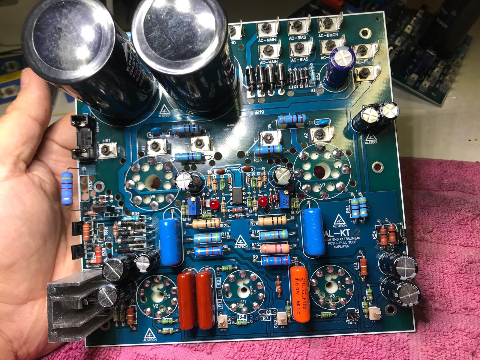
Figure 1 shows the complete circuit of a power amplifier channel. It consists of five amplification stages, a high voltage power supply (HT), a negative bias power supply (Bias) and the filament power supply (Heaters). Everything is found on just one printed circuit board, unlike other projects. Below are pictures of the assembly of the circuit on the board.
На рис. 1 показана полная схема канала усилителя мощности. Он состоит из пяти каскадов усиления, источника питания высокого напряжения (HT), источника питания с отрицательным смещением (Bias) и источника питания накала (Heaters). Все находится всего на одной печатной плате, в отличие от других проектов. Ниже представлены фотографии сборки схемы на плате.
OBS: Estas placas servem para a montagem da grande maioria das válvulas tetrodo ou pentodo de potência (saída) que possuam base octal (8 pinos), apenas com a mudança de alguns valores de resistores na placa. Sendo, os respectivos transformadores de força e de saída compatíveis com as válvulas utilizadas. Também possui na placa um circuito auxiliar para a monitoração da corrente de Bias através de um LED por válvula.
NOTE: These boards are used to assemble the vast majority of tetrode or power pentode tubes (output) that have an octal base (8 pins), just by changing some of the resistor values on the board. Therefore, the respective power and output transformers are compatible with the tubes used. It also has an auxiliary circuit on the board for monitoring the Bias current through an LED per tube.
ПРИМЕЧАНИЕ: Эти платы используются для сборки подавляющего большинства ламп тетрода или силового пентода (выход), которые имеют восьмеричную базу (8 контактов), просто изменив некоторые номиналы резисторов на плате. Поэтому соответствующие силовые и выходные трансформаторы совместимы с используемыми лампами. Он также имеет вспомогательную схему на плате для контроля тока смещения через светодиод на каждой трубке.
Esta placa de circuito impresso se encontra a venda somente por contato direto pelo telefone ou watzap +55 14 99134-0330, no email andrelimarodrigues@gmail.com e também disponibilizo placas de outros projetos, Veja meus outros artigos neste blog.
This printed circuit board is for sale only by direct contact by phone or whatsapp +55 14 99134-0330, at andrelimarodrigues@gmail.com and I also make boards from other projects available, see my other articles on this blog.
Эта печатная плата продается только при прямом контакте по телефону или WhatsApp +55 14 99134-0330, по адресу andrelimarodrigues@gmail.com, а также я делаю платы из других проектов, см. другие мои статьи в этом блоге.
 | |
| Sugestão de montagem em stereo com KT150 |


contato: +55 (14) 99134-0330 (Andre) - andrelimarodrigues@gmail.com
Retornar a página inicial do blog.

Parabéns pela matéria
ResponderExcluirSó há pouco tempo descobrir através de uma publicação em uma revista nacional que existe este amplificador nacional e que foi avaliado positivo pelos críticos da revista, certamente irei fazer um esforço para conhecer este projeto que no mercado nacional talvez seja o primeiro a ter tal reconhecimento.
ResponderExcluirParabéns pela iniciativa do André.
Obrigado pelo comentário mesmo que anônimo, está faltando incentivo neste país a novas iniciativas, mas que seja sérias e que se compromentam com a verdade, este é meu pensamento!
ResponderExcluirObrigado
Alstech fica em Lins - SP , em um prédio acho que no centro .
ResponderExcluirMuito bom seu artigo André, parabéns.
ResponderExcluirEsquema do amplificador KT 150 NAO COMSIGO LER O ESQUEMA, ESTA SEM NITIDEZ, TEM COMO MELHOR, POR FAVOR ?
ResponderExcluir